ADVERTISEMENT
 |
| A simple SWR analyzer with ili9341tft and ad9850 DDS |
A simple antenna analyzer is a helpful gadget which will tell us about the frequencies to which a piece of wire will resonate on. This is very useful in conjunction with a simple tuner to adjust the antenna for an optimum VSWR (voltage standing waves ratio). Usually, a good commercial antenna analyzer is an expensive device which we use once in a while. Here is a simple project which will give a rough estimation of VSWR and resonant frequencies of a random piece of wires, antennas and lc networks. For the critical reader, there is a lot of limitations within this simple design and can read more about various possibilities here (keywords: harmonics, directional coupler, superheterodyne).
This project uses a simple ad9850 module as its heart to generate the rf signals for the sweep. The controller is an Arduino pro mini (with an atmega328 running on 3.3volt) and for display, it uses an ili9341 tft.
The core circuitry for the analyzer is very simple and is based on the design from Beriks (K6BEZ) simple antenna analyzer (pdf). I added a buffer with the DDS generator (as shown on W5DOR).
To control the whole circuitry, I added an IR receiver which is useful for inputting frequencies, setting up the scan, span, etc. (basics on ir library). There is an updated version which uses a rotary encoder at the bottom of the page [Rotary Encoder]
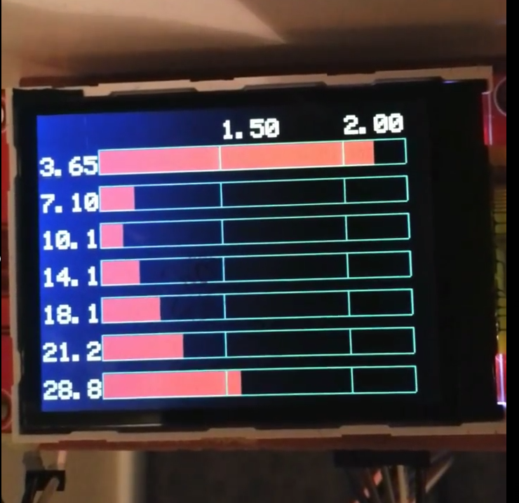
So currently the firmware supports three things, a simple DDS VFO, a VSWR plot with a sweep from 1-30mhz and can be adjusted to smaller regions for e.g 7.000MHZ to 7.500 MHZ.
 |
VSWR plot from Arduino antenna analyzer on an ili9341tft
|
There is a quick band scanner which scans all amateur radio bands and locates the best band which suits the antenna.
 |
| Scanning the bands |
 |
| Arduino DDS menu |
Here is a simple video of the analyzer connected to a parallel lc circuit with a 50ohm carbon resistor to use it as a simple scalar network analyzer (filter around 7mhz)
Here is some more pictures to show the constructions
 |
| DDS and controller together with display |
 |
| buffer, opamp, and detectors |
 |
| building blocks |
 |
| PC interface |
 |
| Componets/modules |
 |
| Finished assembly |
- Get the Arduino and LCD communicate and display the basic test patterns. See this post on getting the ili9341 up and running. It basically uses a simple library for drawing on the TFT and I modified it a bit to get the correct display orientation (So use the ili9341 library here)
- Test the ad9850 module and the Arduino to work together: See this post.
- Now get the Timed action, Infrared Remote and ad9850 libraries.
- Assemble the SWR bridge board with buffer and adjust the potentiometer on the forward power to get a voltage output in the ADC range (0-3.3v). Set the DDS module to a fixed frequency and do the measurements (for e.g set 10mhz ) and do the same with a sweep. You could use the k6bez antenna analyzer script to test it first, which has the necessary functions to test and calibrate the circuit. See the link in the reference below (Note: adjust the sketch to match the pins (2,7,9,8)of your DDS module)
- Upload the script and open a serial console. Keep pressing a remote control (any make) and assign the keys to different function by copying the number shown for specific buttons to the relevant areas in the sketch.
A quick and dirty schematic (hand drawn) is attached below. It is basically derived from reference [1] and [3]. The construction used some simple pro-typing boards. RF sections could be better constructed on a copper clad in Manhattan style. Here I used a simple stripboard and attached a ground plane with a conductive tape (separated by a plastic film).
 |
| Crude Schematic for the analyzer. This is my first version and used an IR remote. The code is at https://raw.githubusercontent.com/riyas-org/swranalyser/master/antenna_light_tft/antenna_light_tft.ino ALWAYS FOLLOW THE PIN NUMBER USED IN THE SKETCH as there are some typos and errors. |
Here is a simple version of the VSWR analyzer using a rotary encoder with a click. The connection is simple. Connect the center pin and one side of the click (button) to the ground. The other end of the click switch is connected to A0 pin and a library is used to detect single and double clicks (Onebutton). The other two pins on the encoder (of the three) are connected to pin 2 and 3 of the Arduino (interrupt). There is a slight change in the wiring for ad9850 DDS module which is connected to pin 9,8,7 and 10. Backlight on the TFT is directly connected to 3.3v via a current limiting resistor.
See this post for testing rotary and TFT - Adding Rotary encoder to arduino projects- quick start
Connections
Attached a simple hand drawn block schematic for several modules. The VSWR bridge circuitry is same as k6bez. Alternatively, an ad8307 based rf sense circuitry can be used. Ensure that the output of the rf sense is adjusted to fall within the ADC range (here 0-3.3v). A 5v design needs a level shifter for the TFT module.
 |
| Block schematic for the standalone analyzer with rotary encoder and Bluetooth serial (click to enlarge) Always double check the wiring as sometimes errors creep in. See the comments in the Arduino sketch to get an idea on which pin gets connected |
1) If running with a pro-mini on 3.3 volts, make sure that the fwd and rev voltages from detector fall wit in the ADC range (0-3.3volt)
2) Buffer amplifier design is actually for 12 volts. I was running it at 5.5 volts (make sure it is 5.5 with a multimeter, do not trust the wall wart) and got good results. To test it, add a 100-ohm resistor to the antenna port and run the analyzer to get a flat line. If the SWR rolled up at the higher frequencies, it means the buffer is not working well. An alternative is to replace 1k resistors with 220 ohms and the emitter resistor (470)with 220 for lower voltage. Also, add a rf choke to the buffer power supply with a 0.1 cap to decouple.
3) An alternative solution is to run the pro mini at 5 volts and will give a wider ADC (0-5v) at the cost of a level shifter.
4) Use a directional coupler to replace the resistive bridge. Use an ad8307 log detector.
5) Adding a superheterodyne detector to get rid of harmonics and drive the mixer using a multiple clock generator (e.g Si5351) and use other channels to feed the sweeper/buffer.
 |
| Effect of inadequate power supply to buffer |
A few more pictures of the prototype in an earbud case :)


Hex File for atmega328 (Download)
Source Code (Download)
1 2 3 4 5 6 7 8 9 10 11 12 13 14 15 16 17 18 19 20 21 22 23 24 25 26 27 28 29 30 31 32 33 34 35 36 37 38 39 40 41 42 43 44 45 46 47 48 49 50 51 52 53 54 55 56 57 58 59 60 61 62 63 64 65 66 67 68 69 70 71 72 73 74 75 76 77 78 79 80 81 82 83 84 85 86 87 88 89 90 91 92 93 94 95 96 97 98 99 100 101 102 103 104 105 106 107 108 109 110 111 112 113 114 115 116 117 118 119 120 121 122 123 124 125 126 127 128 129 130 131 132 133 134 135 136 137 138 139 140 141 142 143 144 145 146 147 148 149 150 151 152 153 154 155 156 157 158 159 160 161 162 163 164 165 166 167 168 169 170 171 172 173 174 175 176 177 178 179 180 181 182 183 184 185 186 187 188 189 190 191 192 193 194 195 196 197 198 199 200 201 202 203 204 205 206 207 208 209 210 211 212 213 214 215 216 217 218 219 220 221 222 223 224 225 226 227 228 229 230 231 232 233 234 235 236 237 238 239 240 241 242 243 244 245 246 247 248 249 250 251 252 253 254 255 256 257 258 259 260 261 262 263 264 265 266 267 268 269 270 271 272 273 274 275 276 277 278 279 280 281 282 283 284 285 286 287 288 289 290 291 292 293 294 295 296 297 298 299 300 301 302 303 304 305 306 307 308 309 310 311 312 313 314 315 316 317 318 319 320 321 322 | /* A simple vswr analyser using atmega328, a resistive bridge and a diode detector Compared to my previous one, this is modified to support a rotory encoder Usage: Single click on the encoder: Move across menu Double click will select Rotation is used to change the values More: http://blog.riyas.org */ #include <stdint.h> #include <TFTv2.h> //https://github.com/riyas-org/ili9341 #include <SPI.h> #include <avr/eeprom.h> #include <AH_AD9850.h> //http://www.arduino-projekte.de/index.php?n=7 #include <OneButton.h> //https://github.com/riyas-org/OneButton #include <Rotary.h> //https://github.com/riyas-org/Rotary #define SWR_STEP 64 //set it high for more points in the plot Rotary r = Rotary(3, 2); // Encoder connected to interrupt pins 2 and 3 on arduino promini (atmega328) OneButton button(A0,true);// Click button on the encoder the other end is connected to ground AH_AD9850 AD9850(9, 8, 7, 10); //AH_AD9850(int CLK, int FQUP, int BitData, int RESET); // Pins for Fwd/Rev detectors const int REV_ANALOG_PIN = A2; const int FWD_ANALOG_PIN = A1; //const int EXTRA_ANALOG_PIN = A3; // an extra detector for rf power const byte lcdW = 320 ; const byte lcdH = 240 ; const byte fontWidth = 10 ; const byte fontHeigth = 30 ; const byte totSpan = 9; float spanValue[totSpan] = { 25000.0, 50000.0,100000.0, 250000.0,500000.0, 1000000.0, 2500000.0, 5000000.0,10000000.0 } ; byte SWR[SWR_STEP]; //byte PWR[SWR_STEP]; float minSwr; float maxSwr; uint32_t next_state_sweep = 0; byte menu_redraw_required = 0; byte doubleClicked = 0; byte modSpan = 0; byte posInput = 0; byte sign = 0; // negative float Swr ; float Pwr ; struct settings_t { int spanIdx; float freqCenter; } settings; //averaged analogue read slow but solid double analog_read_value(int pin) { double total = 0.0; double reading; int i; for (i=0; i< 80; i++) { reading = analogReadX(pin); total += reading * reading; } return total / 80.0; } double analogReadX(const int pin) { if (pin==FWD_ANALOG_PIN) //in my case forward reading has an offset return analogRead(pin); else return analogRead(pin)-17; } void Docalcswr(){ double FWD=0; double REV=0; double VSWR; // Read the forawrd and reverse voltages REV = analog_read_value(REV_ANALOG_PIN); FWD = analog_read_value(FWD_ANALOG_PIN); if(REV >= FWD){ // To avoid a divide by zero or negative VSWR then set to max 999 VSWR = 999; } else { // Calculate VSWR VSWR = (FWD+REV)/(FWD-REV); // Rx=(25+REV)/(0.5*FWD-REV-0.5); Swr = abs(VSWR); // Pwr = sqrt(analog_read_value(EXTRA_ANALOG_PIN)); } } void creaGrid() { byte p0 = lcdH - 2; for (int i = 0 ;i < 9; i++) { Tft.drawVerticalLine((i*40),fontHeigth,164,RED); //240*320 } for (int i = 1 ;i < 2; i++) { Tft.drawHorizontalLine(0,i*82+fontHeigth,319,RED); //240 } Tft.drawCircle(160,164+fontHeigth,5,GREEN); if (settings.freqCenter >9999999) Tft.drawFloat(settings.freqCenter/1000000,130,214,2,YELLOW); else Tft.drawFloat(settings.freqCenter/1000000,130,214,2,YELLOW); float s = spanValue[settings.spanIdx]/8; for (int i = 0 ;i < 9; i++) { double freq = (settings.freqCenter + (i-4)*s)/1000000; Tft.drawFloat(freq,(i*40),185,1,YELLOW); } if (spanValue[settings.spanIdx] >9999999) Tft.drawFloat(spanValue[settings.spanIdx]/1000000,260,214,2,YELLOW); else Tft.drawFloat(spanValue[settings.spanIdx]/1000000,260,214,2,YELLOW); Tft.drawRectangle(0,fontHeigth,320,164, GREEN); Tft.drawString("SWR",0,0,2,CYAN); Tft.drawFloat(minSwr,40,0,2,GREEN); Tft.drawFloat(maxSwr,120, 0,2,RED); if (!modSpan) { Tft.fillRectangle(40,210, 60,20, CYAN); Tft.drawString("freq",40, 210 ,2,BLUE); Tft.drawString("span",210, 210 ,2,BLUE); } else { Tft.fillRectangle(210,210, 50,20, CYAN); Tft.drawString("freq",40, 210 ,2,BLUE); Tft.drawString("span",210, 210 ,2,BLUE); } } void printSwr() { for (int k = 0;k < SWR_STEP; k++) { int spacer=320/SWR_STEP; Tft.drawLine(k*spacer,SWR[k],(k+1)*spacer,SWR[k+1],WHITE); //plot vswr //Tft.drawLine(k*spacer,PWR[k],(k+1)*spacer,PWR[k+1],GREEN); //plot power } } void showCursor(int x0, int y0) { Tft.fillRectangle(x0,y0, 50,8, BRIGHT_RED); } void draw(void) { Tft.fillRectangle(0, 0, 320, 240, BLACK); creaGrid(); printSwr(); if (doubleClicked == 1) { switch (modSpan) { case 0 : { if (posInput <3) posInput = 3; showCursor(130,235); break; } case 1 : { posInput = 6; showCursor(260,235); break; } default: break; } } } void setup(void) { Tft.TFTinit(); // init TFT library Tft.fillRectangle(0, 0, 320, 240, BLACK); analogReference(DEFAULT); // initialize serial communication at 9600 bits per second: Serial.begin(9600); //rotory interrupt PCICR |= (1 << PCIE2); PCMSK2 |= (1 << PCINT18) | (1 << PCINT19); sei(); //set up the click on the encoder button.attachDoubleClick(doubleclick); button.attachClick(singleclick); eeprom_read_block((void*)&settings, (void*)0, sizeof(settings)); if (settings.freqCenter <= 0) { settings.freqCenter = 7000000.0; } settings.spanIdx = 8; //settings.freqCenter = 7000000.0; AD9850.reset(); //reset module delay(200); AD9850.powerDown(); //set signal output to LOW AD9850.set_frequency(0,0,settings.freqCenter); } void calcParameters(int k, float stepSpan) { float freq; float tempSwr; //float tempPwr; freq = settings.freqCenter + (k-SWR_STEP/2)* stepSpan; if (freq <= 0) freq = 1000000.0; AD9850.set_frequency(freq); delay(1); Docalcswr(); Swr = max(1.00,Swr); //Pwr= max(1.00,Pwr); //tempPwr= min (600, Pwr); //Serial.print("temppwr:"); //Serial.println(tempPwr); minSwr = min(minSwr,Swr); maxSwr = max(maxSwr,Swr); tempSwr = min (3.0, Swr); SWR[k] = 30+(164 - round(82*(tempSwr - 1))); //MAX SWR = 3.0 164+fontHeigth //PWR[k] = 30+(164 - round(164*((tempPwr*tempPwr)/360000))); //Pwr; } uint8_t update_graph(void) { Tft.fillRectangle(250, 0, 70, 20, BLUE); Tft.drawNumber(next_state_sweep,250,0,2,CYAN); if ( next_state_sweep < SWR_STEP) { if(next_state_sweep == 0) { minSwr = 10.00; maxSwr = 1.00; } float s = spanValue[settings.spanIdx]/SWR_STEP; calcParameters(next_state_sweep,s); next_state_sweep++; return 0; } else { next_state_sweep = 0; return 1; } } float updateFreq(double r, float v) { float step = round(pow(10,posInput)); if (r == DIR_NONE ) { // do nothing } else if ((r == DIR_CW) && (v + spanValue[settings.spanIdx]/2 < 54000000.0)) { v = v + step; } else if ((r == DIR_CCW) && (v >= step + 1000000.0)) { v = v - step; } return v; } void updateSpan(double r) { if (r == DIR_NONE ) { // do nothing } else if (r == DIR_CW) { settings.spanIdx++; } else if (r == DIR_CCW) { settings.spanIdx--; if (settings.spanIdx < 0) settings.spanIdx = totSpan -1; } settings.spanIdx = settings.spanIdx % totSpan; } void routine(void) { if ( update_graph() != 0 | menu_redraw_required != 0) { draw(); } menu_redraw_required = 0; // menu updated, reset redraw flag } void loop() { // keep watching the push button: button.tick(); routine(); } ISR(PCINT2_vect) { //Serial.println("interrupt"); unsigned char result = r.process(); if (doubleClicked) { if(modSpan){ updateSpan(result); } else { settings.freqCenter = updateFreq(result, settings.freqCenter); } } else modSpan = !modSpan; menu_redraw_required = 1; } void singleclick() { //change position in field //Serial.println("Single"); if (doubleClicked) { posInput++; posInput = posInput % 7; } menu_redraw_required = 1; } void doubleclick() { //change field //Serial.println("double"); doubleClicked = !doubleClicked; if (!doubleClicked) eeprom_write_block((const void*)&settings, (void*)0, sizeof(settings));; menu_redraw_required = 1; } |
Simple schematic for analyser with encoder
Here is a simple attempt to draw a schematic in eagle cad. If some one can help out with a nicer one, please drop an email or comment
 |
| Schematic for the analyser with encoder |
Partlist
| Part | Value | Package | Description |
| C1 | 1u | C050-025X075 | CAPACITOR, European symbol |
| C7 | 1u | C050-025X075 | CAPACITOR, European symbol |
| C8 | 100n | C050-025X075 | CAPACITOR, European symbol |
| C9 | 10n | C050-025X075 | CAPACITOR, European symbol |
| C10 | 100n | C050-025X075 | CAPACITOR, European symbol |
| C11 | 10n | C050-025X075 | CAPACITOR, European symbol |
| D3 | AA143 | DO204-10 | DIODE |
| D4 | AA143 | DO204-10 | DIODE |
| IC2 | LM358N | DIL08 | OP AMP also LM158; LM258; LM2904 |
| PROMINI3.3VOLT | PRO-MINI-2 | PRO-MINI-2 | Arduino Pro Mini Layout 2 |
| R1 | 470 | V234/12 | RESISTOR, European symbol |
| R2 | 1k | V234/12 | RESISTOR, European symbol |
| R3 | 100 | V234/12 | RESISTOR, European symbol |
| R4 | 5k | V234/12 | RESISTOR, European symbol |
| R12 | 50 | V234/12 | RESISTOR, European symbol |
| R13 | 50 | V234/12 | RESISTOR, European symbol |
| R14 | 50 | V234/12 | RESISTOR, European symbol |
| R15 | 50 | V234/12 | RESISTOR, European symbol |
| R16 | 100k | V234/12 | RESISTOR, European symbol |
| R17 | 5k | V234/12 | RESISTOR, European symbol |
| R18 | 648 | V234/12 | RESISTOR, European symbol |
| R19 | 10k | V234/12 | RESISTOR, European symbol |
| R20 | 100k | RDH/15 | RESISTOR, European symbol |
| R21 | 5k | V234/12 | RESISTOR, European symbol |
| R22 | 648 | V234/12 | RESISTOR, European symbol |
| R23 | 47 | V234/12 | RESISTOR, European symbol |
| SW1 | EC12E_SW | ALPS_EC12E_SW | ALPS rotary Encoder EC12E series with switch |
| T2 | 2N2222 | TO18 | NPN TRANSISTOR |
| T3 | 2N2222 | TO18 | NPN TRANSISTOR |
| U$2 | 2.2_TFT_LCD | 2.2_TFT_LCD | |
| U1 | AD9850 DDS Module | DDS_AD9850 | AD9850 DDS Module |
| X2 | BNC | AMP_227161 | JACK, RIGHT ANGLE, 50 OHM, PCB, BNC |
References
[1] http://www.hamstack.com/hs_projects/k6bez_antenna_analyzer.pdf
[2] http://iphone-atom1945.blogspot.com/2013/08/antenna-analyzer-arduino-uno-dds-ad8307.html
[3] http://www.zl2pd.com/digitalZmeter.html
[4] https://github.com/devzendo/antenna-analyser-c
When publish firmware
ReplyDeleteCan you publish a PartList an athe Arduino Source?
ReplyDelete73 de Christian
I will soon be updating it on github. AA143 was a bit difficult to get , but i guess a good alternate solution is to use an ad8307 for rf detection.
DeleteOther important parts were
1) Arduino promini (from ebay)
2) ili9341 tft display
3) TSOP 1738 ir receiver
4) Any ir remote
5) Stripboard and connectors
6) LM324,2n2222 assorted resistors and caps
7) AD9850 dds module from ebay
73s
are looking forward to
ReplyDeletean error : antenna_light_tft.ino: In function 'void showCursor(int, int)':
Deleteantenna_light_tft.ino:176:36: error: 'BRIGHT_RED' was not declared in this scope
You need the library for the ili9341. It is available from gmtii on github. (See the previous post to get the display working ie getting started with ili9341)
DeleteWhy inverted display
DeleteColour? Can you send a picture?
DeleteI can send
DeleteIt seems the orientation of the display is wrong, so you are missing a part of the swr chart. Now i remember i modded somewhere in the library to get it in landscape. I will update it on github/ will mail you.
DeleteBest regards
Thanks, I'll wait
ReplyDeletehttps://github.com/riyas-org/ili9341
DeleteThis is great stuff...
DeleteHi, I faced the same issue as the wrong orientation issue.. could you edit yr original documents above links to point them to the modded ili9341 library instead...
Thanks Stanley! updated
DeleteHi Riya,
DeleteI am trying your code for encoder use and so far so good. I am not able to find any updated code that will allow the display to display landscape rather than portrait. The analyzer .ino I am using is the version shown on this page.
Am I missing something (most likely!) and can you point me in the right direction?
Thanks & 73's
Mark - WT6P
Hi Mark, use the mdified tft library from my github: https://github.com/riyas-org/ili9341
Delete73s
Riyas
Dear Riya,
ReplyDeleteFirstly, you did a great job combining them together to make this 2.2" antenna analyzer...
I've setup the circuit on the breadboard...
I've a few thing that I do not understand... hope you can enlighten me..
1. Using yr current sketch, when I probe various point with an osciloscope, the output freq is constant at 125Mhz ..
Which function in the code are for setting the freq sweep ?
2. What are the IR buttons for ?
singleclick ?
doubleclick ?
longclick ?
centerset ?
3. I didn't see the "quick band scanner" screen ? Was it disabled in the current codes posted on github..
4. How do I set the 10k POT in A0 ? How do I calibrate it ??
I usually put a 50ohm terminator at the end of a bnc plug ...
Thanks for the comments. See update_graph_band(void) which does the sweep for bands and see void calcParameters(int k, float stepSpan), which does sweep for the chart. If you look closer at the function void calcParameters(int k, float stepSpan), you can see that the array SWR[] getting filled and will then gets plotted. I recommend you to upload the sketch from K6BEZ in the beginning to calibrate the analyser. I will detail it here when i get some more time.
DeleteIt seems your dds is not getting the control signals. Try using AD9850.set_frequency(freq); in the set up to see if dds works fine
IR buttons are not fixed. You have to manually assign them with the ir codes. Basically the longclick will cycle through the different options ie VSWR chart mode, Band mode and DDS mode. Double click will cycle through the menu and single click will increment/decrement values. Centerset was used for a debug where it set the maximum scan range when the analyser is in swr charting mode.
Calibration is same as K6BEZ analyser. Put the terminator and adjust for minimum swr. In the beginning make sure that the voltage variation is in the adc range. I used analogReference(DEFAULT); but you can think of other possibilities here.
I know this post is a fast and dirty one even for an expert home brewer. These days am very busy with several other boring things and sadly missing the hobby and blog. Once things are settled, i will try to make a better discription and i want to upgrade it with a logarithmic rf detector from analog devices (cheap and easy to calibrate)
Thanks for the lengthy reply...
DeleteFor yr circuit, what are the use of the 0.1uF caps before the SWR bridge ??
Without the 0.1uF caps, I'm getting almost 3V but with it, the voltage are too low to trigger the 1N34 diode that I am using...
I noticed other SWR bridge circuit also have this caps there ?
Was it to removed the DC biased voltages ???
i also think the same about 0.1 ( coupling and dc filter). I borrowed it from other designs. I found in34 to behave a bit strangely while AA143 works smoothly. Have a look at http://www.njqrp.org/digitalhomebrewing/breadboard/issue4-SWR.html where they use a compensation for in34 (an extra stage with an opamp with 1n34 which compensates for the nonlinearities in the diode detectors). Alternatively we can use ad8307
Deleteshow circuit with ad8307
ReplyDeleteThis comment has been removed by the author.
ReplyDeletehi, when i am compiling I am getting linked errors of header files.WProg.h,math.h(roundoff),,LPC17xx,contneus errors.can any one tried,please respond
DeleteAVGR
DeleteYou need to open up the Timed Action file in an editor and change "Wprogram.h" to "Arduino.h"
Save and recompile. I had the same problem and this fixed it.
Hello
ReplyDeleteI really like this project and I am trying to get it all ruinning for a possible club project here in St. Louis.
So far I have the TFT, Arduino, Remote and DDS card all operating.
I cannot seem to get it to change modes. I can change the freq. and span but I can't get it to go into the other modes. I have changed all the IRRemote numbers in the code to correspond to my remote but get no response from the 'longclick " button.
Any ideas??
It seems that maybe some code is missing to get it to enter into the other routines once the remote button is sensed.
Larry
Found the problem in the firmware.
ReplyDeleteChanged this line from; select_display = select_display++; to; select_display =++ select_display;
Now it cycles through the three MODES.
Larry
n0sa
Hi all.
ReplyDeleteI am having trouble in compiling this sketch. I think I have all the libraries installed correctly, but it is still throwing these errors at me. I don't have good understanding what error messages mean, but usually can get sketches to run. Any help would be great.
Arduino: 1.0.6 (Windows 7), Board: "Arduino Nano w/ ATmega328"
In file included from C:\Program Files (x86)\Arduino\libraries\TimedAction/TimedAction.h:33,
from antenna_light_tft.ino:14:
C:\Program Files (x86)\Arduino\libraries\TimedAction/WProgram.h:20: error: default argument given for parameter 3 of 'long unsigned int pulseIn(uint8_t, uint8_t, long unsigned int)'
C:\Program Files (x86)\Arduino\libraries\TimedAction/wiring.h:119: error: after previous specification in 'long unsigned int pulseIn(uint8_t, uint8_t, long unsigned int)'
C:\Program Files (x86)\Arduino\libraries\TimedAction/WProgram.h:22: error: default argument given for parameter 3 of 'void tone(uint8_t, unsigned int, long unsigned int)'
C:\Program Files (x86)\Arduino\hardware\arduino\cores\arduino/Arduino.h:224: error: after previous specification in 'void tone(uint8_t, unsigned int, long unsigned int)'
Any help would be great.
Peter
VK2YYO
Hi Peter,
Deleteplease check: http://playground.arduino.cc/Code/TimedAction
This library is used to get rid of a blocking behaviour from the infrared library. A rotory encoder can be used to get rid of the ir remote and this library and i will try to update it whne i get more time
73s
Riyas
Hi Riyas,
ReplyDeleteI have enjoyed this project greatly, but have run into a couple issues I am hoping to get some assistance with. I am using an UNO and the AD9850 with TFT. I have not modified the original analyzer sketch.
These are the current errors and I am at a loss to find the issue:
Arduino: 1.6.6 (Windows Vista), Board: "Arduino/Genuino Uno"
antenna_light_tft:28: error: 'infrared' was not declared in this scope
TimedAction timedAction = TimedAction(100,infrared);
^
antenna_light_tft:29: error: 'routine' was not declared in this scope
TimedAction timedAction2 = TimedAction(100,routine);
^
exit status 1
'infrared' was not declared in this scope
Also, I was wondering if/when you may present the encoder version, rather than the IR version. Thanks for your hard work...Great project!
Mark - WT6P
Hi Mark, thanks for the comments. Exactly now am working on it (its lying on the table) a cleaner version with the encoder which will make it a lot simpler. The ir version need a clean up with a direct input of start and end frequency with number of steps. Please check the Timedaction library (http://playground.arduino.cc/Code/TimedAction)which is used to get the ir remote working without blocking the rest of the code. Please wait a weak or two and will replace it with encoder.
Delete73s
lb7ug/Riyas
Oh Riyas, that is fantastic! I will check out the TimedAction library and see what I can find out. It has been a while since I have programmed in C (have been tied up with HTML for years!) and it is slowly coming back to me.
DeleteI look forward to your revised analyzer, that is exciting.
Tks, 73
Mark - WT6P
Any Info now about this project final version
ReplyDeleteIgor Derivolov Z32ID
Hello, Riyas. I built your antenna analyser, but frequency shows 0.00. I don´t know what is happening. 73. Marcos.
ReplyDeleteTry uncommenting line 191 in setup code.(settings.freqCenter = 7000000) 73s Riyas
DeleteAfter send you a message i founded it...Many tanks.
DeleteRiyas, i need some help:
ReplyDeleteAt lines 61 and 66 appears AnalogReadX and when i remove X my TFT only flash.
In time, what´s the procedure to add scanning bands mode and DDS signal generator?
73.
Good find. AnalogueReadX is used to correct for small offset in readings. The code for band and dds is there in my github. But it is still crude and will update with a better version when i get time. Also the code needs some more optimization to make the plotting and screen refresh faster. 73s
DeleteHi RiYa
ReplyDeletei only got white screen and erratic output from ad9850 when all connected up.
put a 1k resistor from vcc to reset on tft screen and a 1k from ground to reset on ad9850 now working fine,hope this will help.(rotary version).
73 stan(g8ihc)
Hi RiYa.
DeleteI am having trouble in compiling this sketch.
https://i.imgsafe.org/695e2b7.jpg
73! Daniel
Hi Daniel,
DeleteYou have 2 options:
1. Please upgrade your project to the ARDUINO 1.6.5 version. The problem will disappear because the new compiler supports const class members.
2. remove the line 59 "const int _debounceTicks ..." in the OneButton.h file and define it as a global constant using a pre-compiler directive:
#define _debounceTicks 50
in OneButton.h before the class definition (line 25)
Thanks RiYa!
DeleteHi RiYa, I love this project (encoder version). I made some improvements to the design and software.
ReplyDelete1. Added a 5V to 12V converter to provide 12V power the transistor buffer.
2. Starting at line 104, changed:
(a) center frequency position & display to 3 decimal places for adjusting 1Khz.
(b) Added to the display, after center frequency the posInput variable to make it easier know what frequency step is being adjusted (6=1Mhz,5=100Khz,4=10Khz & 3=1Khz)
Code:
104 Tft.drawFloat(settings.freqCenter / 1000000, 3, 75, 214, 2, YELLOW);
Tft.drawNumber(posInput, 160, 214, 2, GREEN); //6=1Mhz,5=100Khz,4=10Khz & 3=1Khz
}
else
{
Tft.drawFloat(settings.freqCenter / 1000000, 3, 75, 214, 2, YELLOW);
Tft.drawNumber(posInput, 160, 214, 2, GREEN); //6=1Mhz,5=100Khz,4=10Khz & 3=1Khz
This a great cheap analyzer that I used to successfully tune all my antennas.
thanks for this post
jerry
Hi Jerry, Just curious here, I deleted line 104,105,106, replace with
DeleteTft.drawFloat(settings.freqCenter / 1000000, 3, 75, 214, 2, YELLOW);
Tft.drawNumber(posInput, 160, 214, 2, GREEN); //6=1Mhz,5=100Khz,4=10Khz & 3=1Khz
}
else
{
Tft.drawFloat(settings.freqCenter / 1000000, 3, 75, 214, 2, YELLOW);
Tft.drawNumber(posInput, 160, 214, 2, GREEN); //6=1Mhz,5=100Khz,4=10Khz & 3=1Khz
and can't compile, I get error message as below:
expected unqualified-id before 'else'
expected unqualified-id before 'else'
Please help ??
Oh OK, I found the problem. there're missing curly brace at the beginning and at the end. problem solved. thanks !
DeleteOLA VOCE CONSEQUIL COOLOCA PRA FUNCIONA PODERIA ME PASSAR O CODICO [email protected]
DeleteHello!Thank you for the project!I'm trying to run it on the Board Arduino UNO.For some reason I have nothing is working, only white screen.I have connected all pins like in the diagram,only UNO,in what could be the problem?
ReplyDeleteYou are welcome. Make sure lcd is compatible with 5 volt !! I guess your uno is running at 5v and the display needs 3.3 volt. Need to use a level shifter. I have tested with a 3.3 volt on uno a while ago (no guarantee on this approach). Just feed uno's vcc pin with 3.3v and do not power it by usb.
DeleteThanks for the great information covered here.
ReplyDeleteI have been working with the analyzer at VK3YY and wanted to upgrade to a TFT display - this web has been very helpful. I see you have a pot to set the swr bridge in the setup - 4. Assemble the swr bridge board with buffer and adjust the potentiometer on the forward power to get a voltage output in the adc range (0-3.3v).
However I dont see anywhere on the schematic where there is a pot shown. I think it would be either R12 or R13 is that correct? Regards Terry M VK4ATM
Thanks Terry for your feedback. I used to write the posts in a hurry so i always miss something. The pot is not on the bridge( the bridge should use exactly 50 ohms except a very small correction if you need to adjust for the capacitance of the antenna connectors used ).
DeleteThe out put from the bridge goes to two OPAMPS (it could be lm324 as in my hand drawn circuit on top of this page or LM358 as in the eagle schematic at the bottom of the page with encoder). This opamps has a variable resistor (10K) connected between its output pins and inverting input pin(4 and 13 for lm324) and a resistor (648 ohm)connected to ground from the inverting input (those -ve marks on opamp). The 10 kilo ohm variable resistor is placed over there and will adjust the gain of that opamp.
There are two opamps used and they will multiply the small voltage from the bridge to a broader range for better read in the atmega328/microcontrollers adc. See http://mustcalculate.com/electronics/noninvertingopamp.php to get an idea on how these resistor and gain works.
An other important thing is if these opamps are run at higher than 5volts, the output may goe above 5 volts which can damage the adc of microcontroller. So keep it under 5v.
73s de lb7ug
Thanks for the info. I have at last been back to this project. The Tft display I purchased lead me on a real chase to get the drivers to work and then to modify the code to suit the altered tft board. Yes it was one of the cheap boards from ebay and I had to change the names to suit the adafruit-tft driver that works with this board.
DeleteA query within the code is used the tft.float variable. I have worked out how to substitute or change almost all other variable wording differences in the code but cant figure out what that variable does. Can you shed some light on that?
You are welcome! If you are refering to Tft.drawFloat function, which is used to write a number with decimals in to the tft screen.
DeleteFor e.g : Tft.drawFloat(settings.freqCenter/1000000,130,214,2,YELLOW);
This will write the center frequency on tft (at location 130,214) with a font size 2 and color YELLOW). So you can replace with some similar function and basically you need to write a float value to screen
So you could use the analyser with for e.g ucg library with some modifications. I used the above code to save some memory to add more features as other libraries took more space on the micro-controller.
I hope this helps.
Nice project, I'm trying to make it. The part with the Arduino and the display works already. I use a larger display, a 2.8 inch ili9341 and it works perfectly.
ReplyDeleteNow I'm trying to draw a PCB for the measuring-bridge and the AD9850.
In the diagram the value from R18 and R22 is ¨648¨, what do you mean by that? This is 680 ohms or 680 k?
And in the diagram, i think R15 will have to be 10k instead of 50 ohms.
Regards, Janbert.
Thanks Janbert. It is in ohms and 680ohm will be fine. The other one is 10k ohm (input to opamp). Regards
ReplyDeleteHi RiYa,
ReplyDeleteNice analyzer ! just wish to know if you're using Arduino 3.3V/8Mhz ? or normal 5V/16Mhz version of Arduino but operate at 3.3V?
3.3v,at 8mhz, also make sure adc voltage wont go above this
DeleteThanks! sure , will adjust the ADC voltage carefully .
Deletehello Riyas
ReplyDeleteI noticed on the diagram that the number of pins of 9850 is reversed.
I would not want anyone could confuse ..
good project.
Flavio IK5ACY
73s
Thanks Flavio.
DeleteVery good project.
ReplyDeleteCan you send me the eagle file?
thanks Isak
Hi RiYa
ReplyDeleteVery nice idea and it seems to run good. I'm working on an other modification of the K6BEZ version of the OM DK2jk. When I'm ready with this version, I will try yours.
By the way, I'm looking for an eagle.lbr for the AD9850 dds modul, there is nothing to find. Any idea?
de 73 Peter - DL6CLM
FUNCIONA NAO TEM MUITO ERRO PERCA DE TEMPO
DeleteLooking at the diodes in signal path, LogAmp, then the cal. impedance.
ReplyDeleteThen the signal full of spurs coming from AD9850. Am I missing something?
A SWR meter is effective if you transmit. OK. Pour 100 Watts to this board and tell what you see!
Is anybody ready to help this programmer to rectify what he wants to see, and how to do that? Deutche Genossen, can you help him? Internet is full of this bullshit and nonsense.
.... .. .-. .. -.-- .-
ReplyDeleteI hope this project is not finished ??? if not, you said treminate with 100 ohm resistor and get a straight line (i did but where should it be ? what swr reading ?) I to used a 2.8" lcd which is a touch sceen module, would you consider writing a sketch using buttons on screen instead of the rotory encoder?(i would do it myself if i had the brain power).Last use lm358 op amp and run the whole thing of a 3.3v reg ????
73's de stan G8IHC
hello, please I ask an info about AD9850:
ReplyDeleteI have just purchased a 6 bands vo using AD9850 but have some problem that don't understand.
It is https://www.amazon.com/AD9850-0-55MHz-Signal-Generator-Digital/dp/B07P57TPCJ
Version of firmware on PIC is displayed at reset, CNS 4.01
I have connected it to a spectrum analyzer.
I have set up IF at 9MHZ
Some band of frequency are ok, and in some bands it has many armonics 3a 5a 7a , and output is a bad sine.
From 1 to 6 MHz , 15 to 20, and 22 to 42 I have no armonics.
From 7 to 15 MHz, 20 to 22 MHz I have many armonics.
Is this normal?
May be the firmware version, that corrupt PHASE of signals or is AD9850 burned?
Sorry but I have not schematic diagram of board. Do you have?
Any advice for me?
many thanks.
Best Regards
73 de IK1ARL , Luciano, Turin, Italy
Hi Luciano, i haven’t used that vfo nor is an expert on the dds chip from analogue device, but i suspect they may have some kind of band pass or low pass filters, which are digitally switched and may be faulty. Either a wrong filter or a wrong switching.
Deletehello and congratulations on your work,
ReplyDeleteI would like to make your antenna analyzer. Could you send me the complete schematic with the power supply voltages. I'm a little lost with this. Thank you in advance. Best regards