ADVERTISEMENT
A simple and stable vfo is an integral part for radio experiments. There are several solutions to generate an rf signal ( Popular ones are : ad9850 dds, Si570 ) for amateure use. Recently the clock generator chip (Si5351A) from Silab is gaining popularity due to its lower cost and ability to generate multiple clock signals (For e.g it can be used as bfo and vfo at the same time)
In this article i will briefly take you to quickly build a simple vfo and then gradually improve it with complexities. There are several articles and libraries available with this chip, but to start with i will try to keep it simple.
Components Needed
Components Needed
- An Si5351A chip with a simple breakout board. it is a very small 3mm X 3mm surface mount device and uses 3.3volt. (Si5351A synthesizer module kit from qrp lab is an example)
- A microcontroller ( i used an arduino uno for making it simple. Those allergic to the word arduino can read it as atmega328, basically we need something to talk with i2c on the si5351, a cheaper solution is an arduino promini from eBay)
- A simple lcd to show what is going on (it can be a digital dial later, i am going to use a 16X2 character lcd with HD44780)
- A rotary encoder with a click (push) button to control the whole stuff in a nicer way
Note: Si5351 is a 3.3volt device and will be destroyed if used at 5 volts, and this voltage limit is also applicable to its communication lines with microcontroller. Hence it needs a level shifter and a 3.3 volt regulator for its usage with a 5volt microcontroller. The good thing is that the current consumption of this clock generator is very low.
Register Settings [http://www.silabs.com/Support%20Documents/TechnicalDocs/AN619.pdf]
Pin connection for Si5351
 |
| Si5351A pin layout |
Vdd and Vddo is 3.3volt, Xa and Xb is connected to a crystal (27mhz) SCL and SDA is connected to a microcontroller (3.3volt maximum) and GND is ground The CLK0-2 are three outputs
A simple level shifter (use two of them)
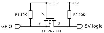 |
| A simple level shifter (BS170 is an alternative) |
Easy solution (Si5351A module from qrp labs) or similar module from adafruit
- Use a MSOP-10/DFN-10 SMD To DIP Adapter and a perforated board
- Etch your own pcb (see: https://github.com/etherkit/Si5351ABreakoutBoard/tree/RevB)
- Aadafruit si5351 clock generator breakout board
- Using a TCXO for making the reference clock more stable
Si5351 modules with all necessary circuitry
 | |
|
 |
| A dirty schematic showing connections for a basic vfo with Si5351 |
Connections and Pins
- LCD RS pin to digital pin 8
- LCD Enable pin to digital pin 9
- LCD D4 pin to digital pin 4
- LCD D5 pin to digital pin 5
- LCD D6 pin to digital pin 6
- LCD D7 pin to digital pin 7
See the LCD pins details in the following figure
 |
| Basic pins of a character LCD |
It is pretty simple if you are familiar with lcd, arduino and rotary encoders and can skip this section. Otherwise for connecting lcd (16 charecters , two lines), there are 6 main connections.
In all cases, connect other pins ie , ground to -ve, LED+ to 5 volt via a 220ohm resister (backlight, may be add a switch or even better we can have an auto power off, later), V0 or display contrast pin is connected to the central pin of a 10k linear potentiometer with other ends to power rails to provide a contrast adjustment). Follow the link here to learn more on character lcd. Ther are even better options with an i2c lcd which we will discuss later.
Connecting the Rotary encoder
DDS Firmware (A simple Si5351 vfo and bfo with S meter for hombrew transceiver- firmware based on arduino/atmega328p)
An encoder has 3 pins and if there is a click /push button there will be 5 pins. More bout the pins and basics of a Rotary encoder in arduino projects can be read in my post on Adding Rotary encoder to arduino projects
Out of the three pins on one side, the central one is connected to ground and the other two pins are connected to interrupt pins (2 and 3 in arduino uno or promini variants). The click button is a simple push to on button which is closed while pressing the shaft of the encoder. One side of the button is connected to ground while the other side to A1 pin of arduino
Si5351 module
Assuming that you are using one or other type of breakout boards with a level shifter to make si5351 tolerant to 5 volt. Connect the SDA and SCL pins of the Si5351 to SDA and SCL pins on the arduino. It is pin A4 and A5 in atmega328 based boards (see manual for arduino mega which has a different layout)
Assembling and testing (step by step)
1) Quick tests for Si5351
Assembling and testing (step by step)
1) Quick tests for Si5351
- Ensure that the voltage input is 3.3 volt: pin 1 of si5351 should show 3.3volt
- If you have an onboard regulator , check its output is 3.3volt
- I used a qrp labs synthesiser module where there is a pin 18 which should read 3.3volt
- Make sure that level shifter is powered correctly. In qrp labs module, pin 11 should be connected to 5 volt
- i2c pins are connected correctly ( ie SDA to SDA (A4 on uno) on arduino and SCL to SCL( A5 on a uno)
(For qrp labs module: pin 1 to ground, pin 10 &11 to vcc, pin 13 to SCL and pin14 to SDA)
 |
| Si5351 vfo module from qrp labs, very clean and easy to use with no hassle for smd soldering (3mm chip) |
Checking Si5351's i2c connection and trouble shooting
Scanning the i2c lines with i2c scanner. Paste the below sketch and load to arduino and set serial port to 9600 and you should get the image below, if things are fine (Note: if you are using an i2c lcd, that will also be listed here. An i2c lcd is very good as it doesnt take any extra pins on the microcontroller!!)
 |
| Checking Si5351 for faults and failed i2c communication. A good sign is a listed device during i2c scan |
Si5351 vfo test sketch
For intial test i used the excellent test sketch from Hans which can be downloaded here Si5351 Test
If you have a different board with a 25MHZ crystal oscillator, just edit the following line from
Upload it and tune the receiver or sdr at 10 Mhz and if everything is fine you will get a signal there
Alternatively, if you have an rtl sdr or a vhf handy, just set the frequency to 144.8Mhz and check the signal. This can be done by editing the Test Sketch with the code as below.
For intial test i used the excellent test sketch from Hans which can be downloaded here Si5351 Test
If you have a different board with a 25MHZ crystal oscillator, just edit the following line from
  #define XTAL_FREQ 27000000 // (27mhz)
                  to
  #define XTAL_FREQ 25000000 (25mhz)
Upload it and tune the receiver or sdr at 10 Mhz and if everything is fine you will get a signal there
Alternatively, if you have an rtl sdr or a vhf handy, just set the frequency to 144.8Mhz and check the signal. This can be done by editing the Test Sketch with the code as below.
void loop()
{
// Do a frequency sweep in 1000Hz steps delay 2.5 second
for(unsigned long frequency = 144800000; frequency < 200001000;
frequency+=1)
{
si5351aSetFrequency(frequency);
delay(2500);
}

}
 |
| Test signal from the Si5351 module viewed with an sdr dongle |
DDS Firmware (A simple Si5351 vfo and bfo with S meter for hombrew transceiver- firmware based on arduino/atmega328p)
i'd like to see how to add RIT, larger displays, if others would also.
ReplyDeletepore memang tong tawwa ☺😀😀
ReplyDeleteI will try to build it let`s see what I will get from it
ReplyDeleteFor some reason, I don't see where the analog signal that drives the S-Meter connects to your VFO. I'm sure it's shown, but I just don't locate it.
ReplyDeleteCan i add if frequency on this firmware ?
ReplyDeletegreat blog, thank you for sharing.
ReplyDeleteHello. Would this sketch be hard to adapt for use with an OLED display instead?
ReplyDeleteThanks
What do you think about this?
ReplyDeletehttps://itshamradio.com/amateur-radio-codes-for-si5351/